Week 09: Output Devices

Energy and output devices
This week's topic was Output Devices. We explored how energy is converted into motion (motors), light (LED diodes), and sound (pressure sensors). We learned about different types of motors (DC motors and MOSFETs, stepper motors, servo motors).
To understand this topic, it is important to grasp the following fundamentals.
Charge
Electrical charge is a property of particles like electrons and protons. Electrons carry a negative charge and protons a positive one. These charges are the reason why electric current can occur when they move.
Voltage
Voltage is a measure of how strongly electrons are "pushed" or "pulled" in a circuit. It can be thought of similarly to the pressure in a water pipe, determining how fast the water can flow. Higher voltage means more "pressure" is applied to move electrons through a conductor.
Current
Current refers to the amount of electrons flowing through a conductor like a wire. The unit for measuring current is the ampere. A stronger current means more electrons are flowing through the wire.
Ohm's Law
Ohm's Law illustrates the relationship between voltage, current, and resistance in an electric circuit. It states that the voltage is equal to the product of current and resistance. If the resistance remains constant, an increase in voltage leads to an increase in current. This law helps in understanding how different components in a circuit work together.
Electromagnetism
Electromagnetic forces are fundamentally important for virtually all modern technologies, including electronics, communication, and electric motors. The interaction between current and magnetism generates motion. Whenever there is a current, there is also an electromagnetic field. The larger it is, the more it can move things - allowing movement in different directions by changing the flow of the current.
Motors
DC MOTORS are electrical motors characterized by their simple construction and versatility. They convert electrical energy into mechanical motion.
A MOSFET is a special type of switch in electronics. It is used to turn electricity on and off or to regulate it. It is controlled by voltage. These switches are very useful and are found in many devices from computers to cars.
A STEPPER MOTOR, also called a stepping motor, is a special type of electric motor that can be divided into precise steps to allow for accurate movements and positioning. Each step corresponds to a small rotational movement, enabling very precise control of the motor's motion
A SERVO MOTOR is a small, powerful motor capable of precise position control. It combines a motor with a position feedback sensor and a control unit. Servo motors can be controlled with Arduino.
Signal Types:
- digitalWrite is a command in many programming languages like Arduino, used to set a digital pin to a specific state. With this command, you can tell a pin to be either "HIGH" (on) or "LOW" (off).
- HIGH: "HIGH" is a state corresponding to an "on" or "active" condition. When a pin is set to "HIGH," it typically has operating voltage, which corresponds to the logic level "1," and the pin outputs a voltage close to the microcontroller's supply voltage (e.g., 5V or 3.3V).
- LOW: "LOW" is the opposite of "HIGH" and represents an "off" or "inactive" state. When a pin is set to "LOW," it is grounded, typically 0 volts, considered as the logic level "0."
Touchpad with SAMD11
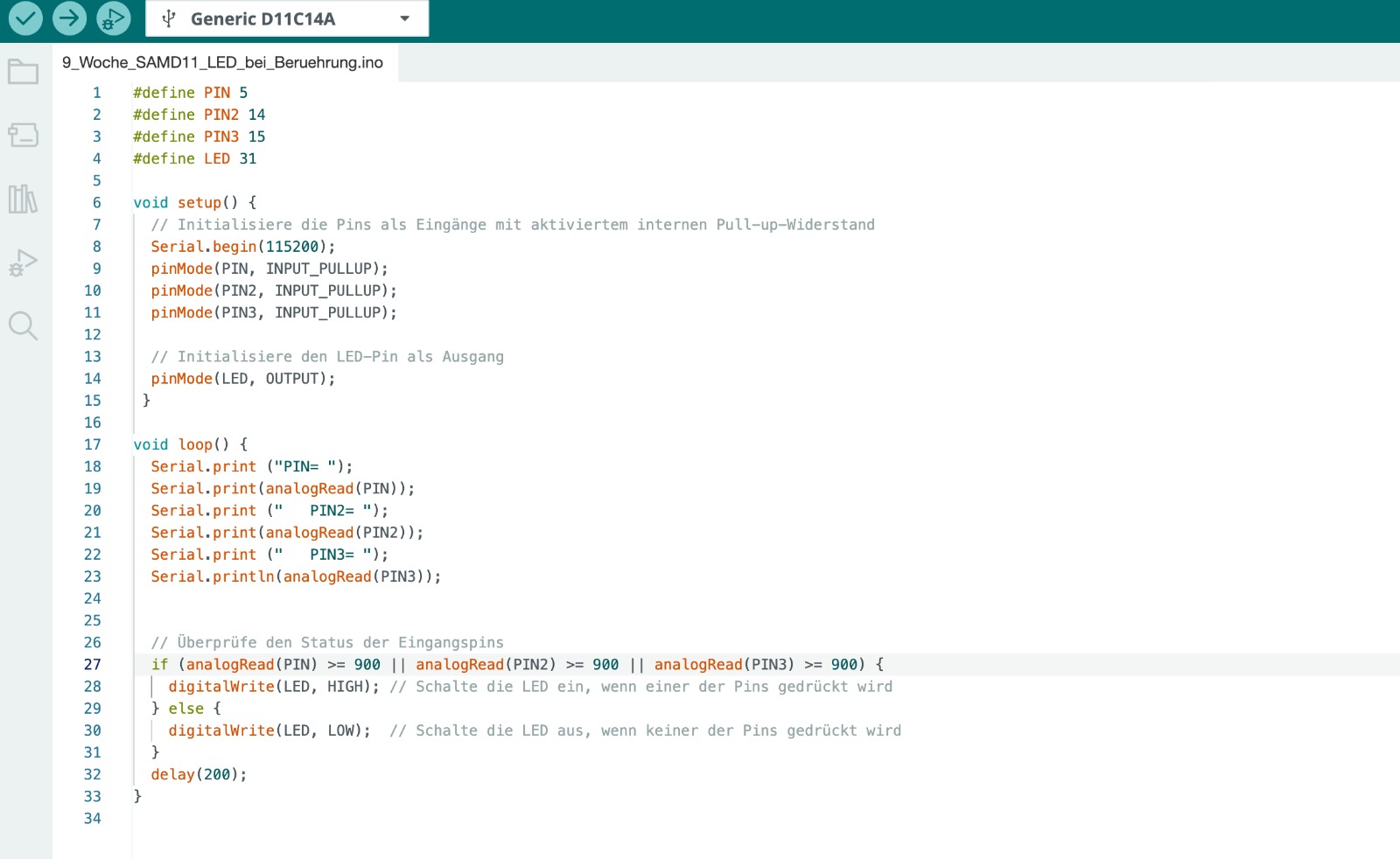
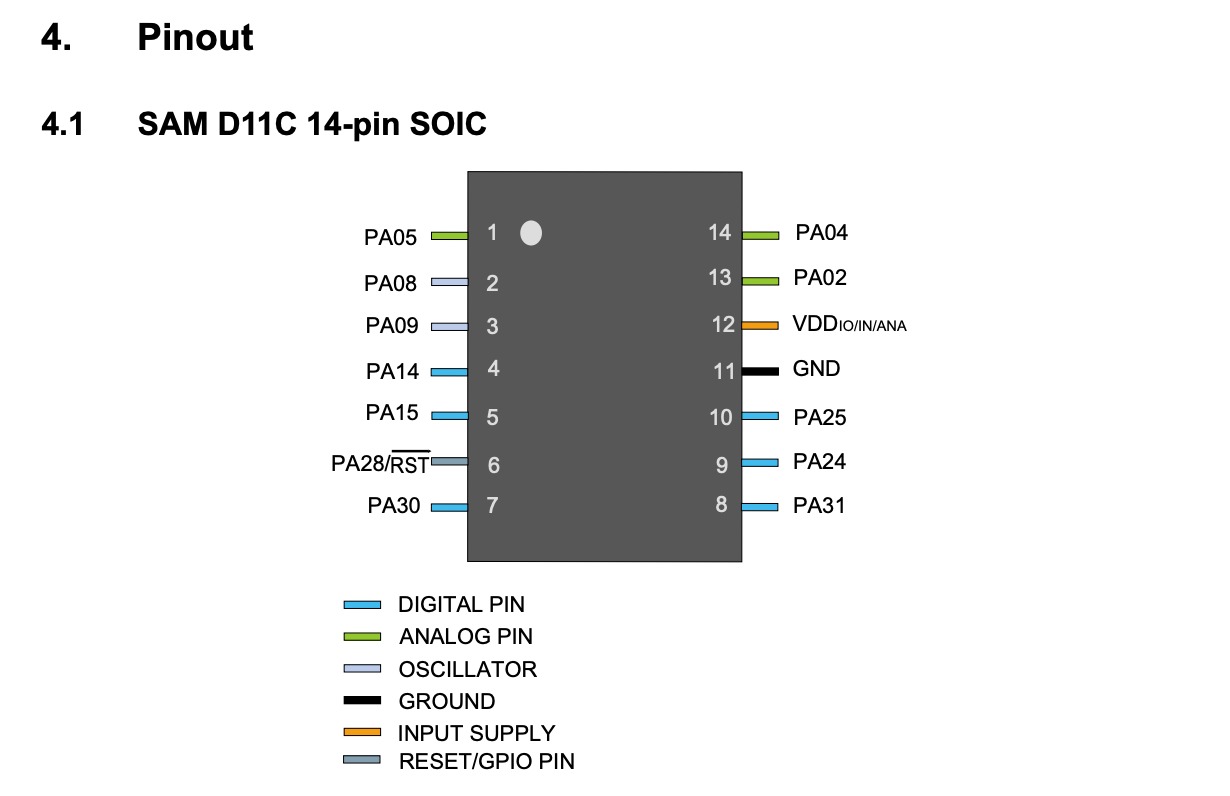
Since I had already programmed my SAMD11 board the previous week, I only needed to modify the code. I wanted to change the code so that the LED would light up only when one of the touchpads is touched. Therefore, I continued to use the LED and included pins 5, 14, and 15 (analog Pins), to which the touch surfaces are connected.
First I defined my Pins:
- #define PIN 5
- #define PIN2 14
- #define PIN3 15
- #define LED 31
Then I defined Pin, Pin2, and Pin3 as INPUT_PULLUP and the LED as an OUTPUT. Finally, I defined that if the analog read of Pin, Pin2, and Pin3 is equal to or higher than 900, the LED should be HIGH, otherwise LOW. I determined the value of 900 by pressing on the pads to read the touch sensitivity.
Arduino
To try out a bit more, I looked for another project. Since I want to work with sound in my final project, I tried the Light Theremin project from the Arduino project book. In this project, a light sensor and a piezo are connected in such a way that the tone produced by the piezo changes depending on the light intensity.
Here are the steps I followed:
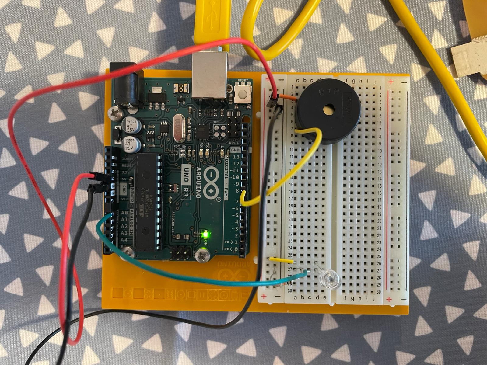
- I connected the breadboard to GND and 5V on the Arduino
- Piezo element: I connected one element to the ground and the other element to digital Pin 8.
- Light sensor: I connected the longer pin to the power supply, the shorter pin to analog Pin 0, and also to GND
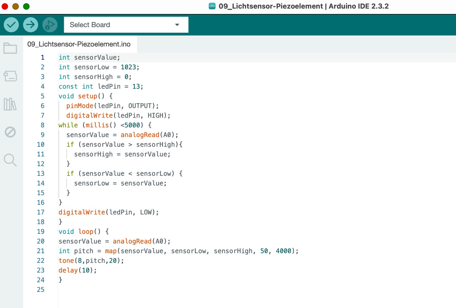
Next, I had to write the program in the Arduino. First, I created variables for the highest and lowest sensor readings: sensorLow = 1023, sensorHigh = 0. Then, I defined the LED pin as 13. I set the LED pin as an OUTPUT and used digitalWrite to set it HIGH. Using a while loop, there is an opportunity to calibrate the sensor by running it in a loop for the first 5 seconds. The initially stated sensor values are then updated. In the loop, the readings from the analog input are taken. I then set sensorLow at 50 and sensorHigh at 4000. Using the tone function (Pin 8), tones are now generated that are determined by the pitch. Depending on the brightness the light sensor detects, the tone changes. In the example, I changed the brightness over the light sensor with my hand.
ESP32-S3-Wroom-1
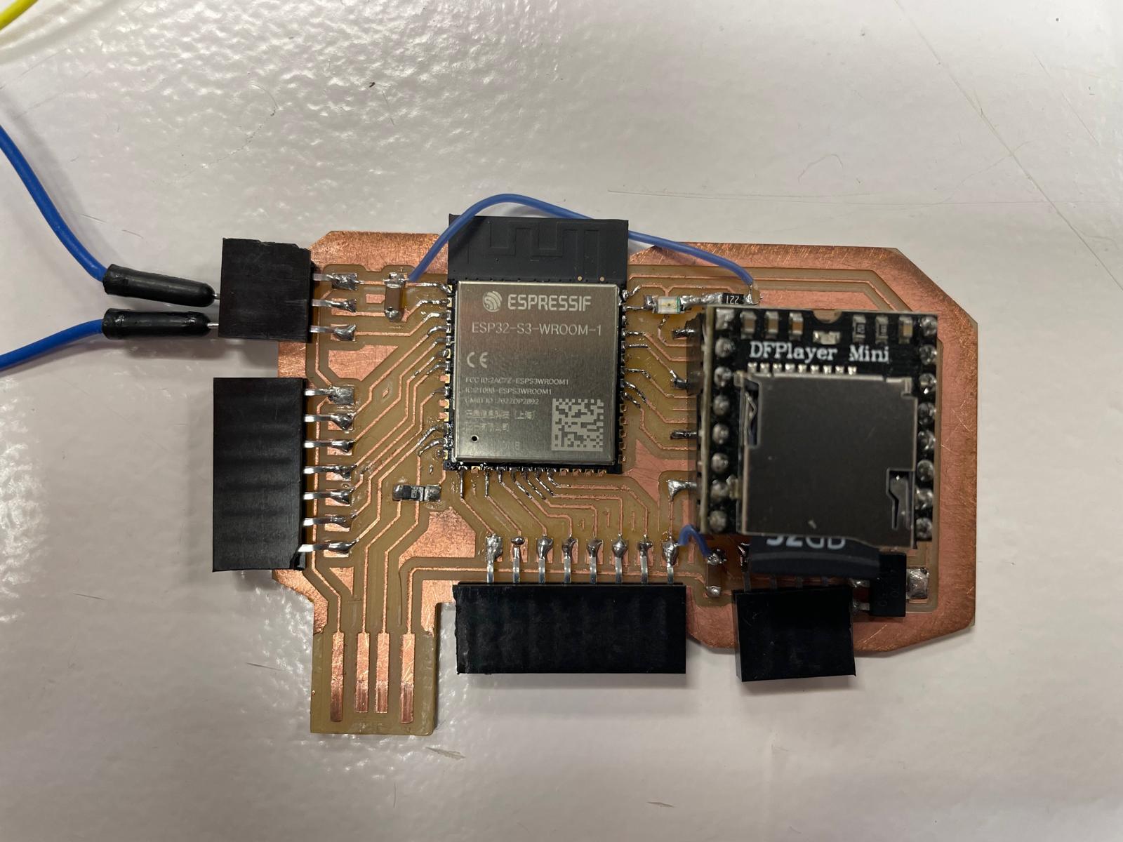
In the previous week, Week 8, I showed how I designed the ESP32-S3-Wroom-1 board. Now I want to demonstrate how I can generate an output with it. For my final project, I want to create sounds. These sounds can be songs, but also other types of tones. First, I want to test generating animal sounds. The ESP32-S3-Wroom-1 communicates via a TX, RX connection with the DFPlayer Mini, which has an integrated SD card and can be connected to speakers. Sounds can be loaded onto the SD card. This connection allows the ESP32 to send commands to the DFPlayer Mini, such as playing specific tracks or adjusting the volume. To better illustrate how the components are integrated, I added a image of the board setup. The image show the wiring connections between the ESP32-S3-WROOM-1 and the DFPlayer Mini. More information about the connection between the touchpads and the board you can finde in Week 11 and on my System Integration side. My goal was to load nine different animal sounds onto the SD card. Initially, I tried to find ready-made files on the internet to download animal sounds as mp3 files. However, this was very difficult because the selection was small and the quality was poor. Additionally, most of the services were not free or cost-effective. Therefore, I decided to record animal sounds from animal movies. This worked well with the recording function of my phone. I then converted the audio files into mp3 files using an online service. After that, I named the files with sequential numbers (1 to 9) and loaded them onto the SD card. With this preparation complete, I could start coding.
Arduino
In the final project, I am working with capacitive touch. The tones are supposed to be generated when the capacitance of the individual touch fields changes. Depending on which touch field is pressed, a different tone should sound. To better control what happens, I structured the code serially.
 First, I defined a TX, RX connection to establish communication between the DFPlayer mini and the ESP32-S3. For this, I connected pins 44 and 43 of the ESP32 to the TX and RX pins of the DFPlayer mini. The connection was already made through the board design, but it also needs to be initialized in the code.
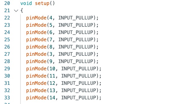 Then I defined touchpads 4 to 14 as Input_Pullups.
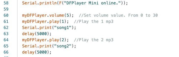 To produce the first output and test if the board works, I programmed it to play the first two sounds in sequence.
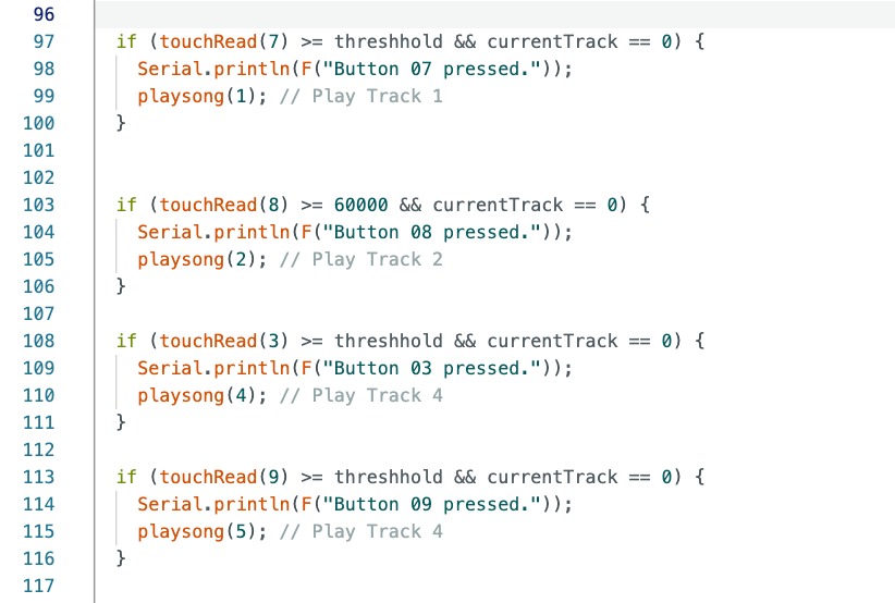 I programmed touchpads 4 and 5 to regulate the volume (lower and higher). All other touchpads are programmed to produce a tone output when one of the touchpads is pressed. As explained in the Input week, I set a threshold value. Once this threshold is exceeded, the tone should play. In the Input week, Week 11, I explained how the threshold can be determined through serial communication. Since the threshold was already established, I could use it and define that songs are played one after another. The code is structured so that it can be read through serial communication whether the touchpad is pressed and which song is played. Since the output is a tone, it can also be heard clearly.
In the following two videos, you can see the output. First through serial communication and in the second video as a tone by pressing the touch fields.
Group assignment
On this page, you will find all the information regarding to our group assignment.